installation, step by step
The fourteen steps of the Protector Guardrail D228 installation manual, transcribed word for word so they can be searched and linked. The manual PDF, with its drawings, is the document that governs the installation.
the fourteen steps
Transcribed verbatim from the manual, including its own spelling, and shown with that step’s own photograph cropped from the same page. Nothing below adds a figure the manual does not state.
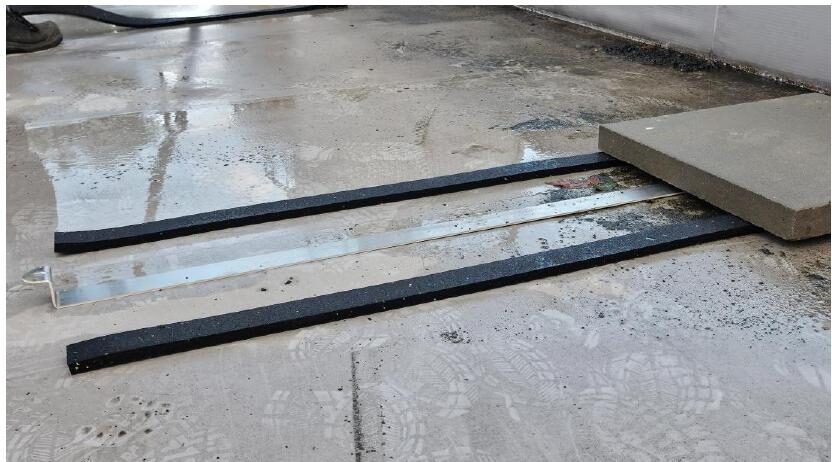
Step 1Place the aluminium tile support strip with the adjustable pedestals and concrete tiles. 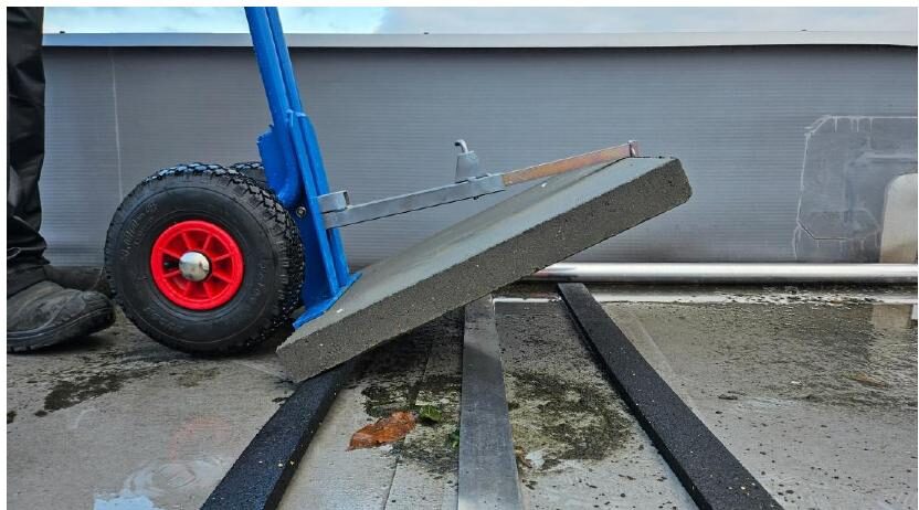
Step 2Use the lifting aid to position the first tiles along the roof edge. 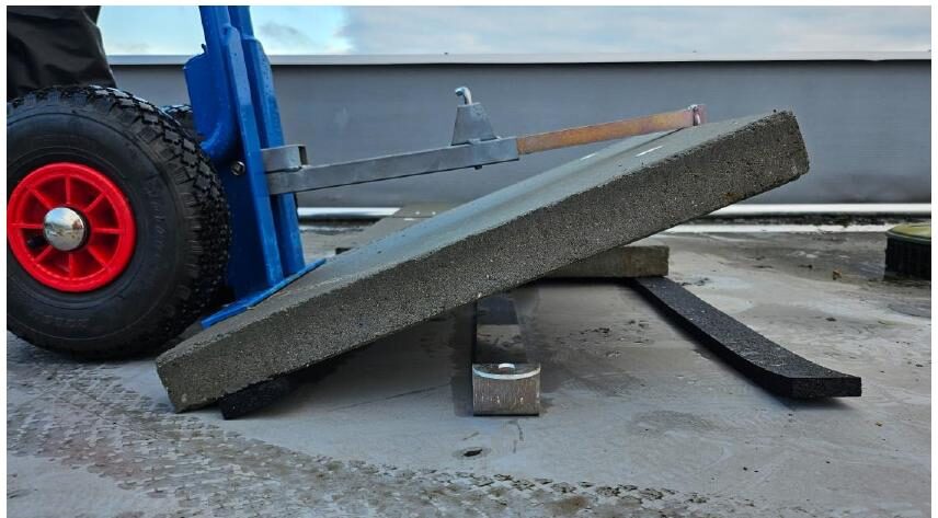
Step 3Continue placing tiles using the lifting aid, ensuring even spacing. 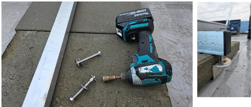
Step 4Position the base post and align the two fastening bolts through the square tube and strip, hand-tighten them to secure initial alignment. 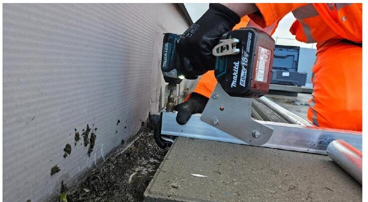
Step 5Attach the horizontal square tube (rail) to the base connection, tighten the front bolt of the strip firmly using a power tool. 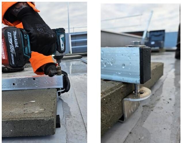
Step 6Tighten the rear bolts of the strip firmly using a power tool. 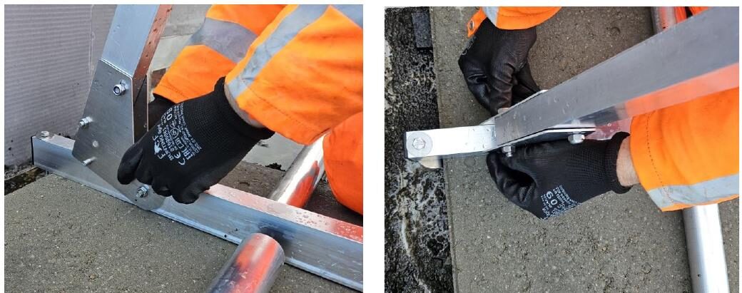
Step 7Ensure the upright post is positioned at 70° or 90° depending on the design. 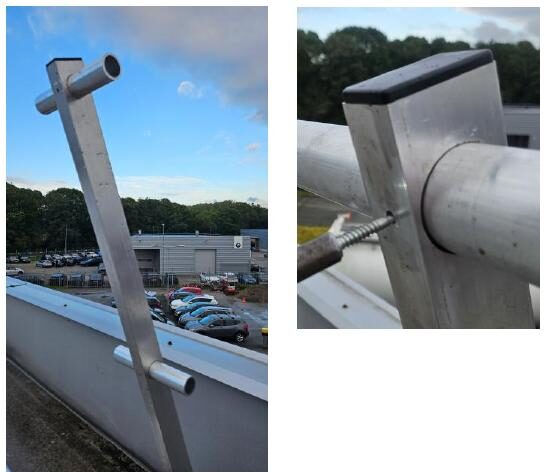
Step 8Install the connection tubes and fasten them to the upright posts. 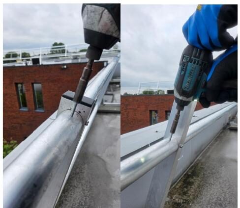
Step 9Tighten all (up and down)tube screws securely for full stability. 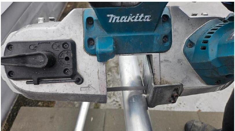
Step 10Cut tubes project designed length. 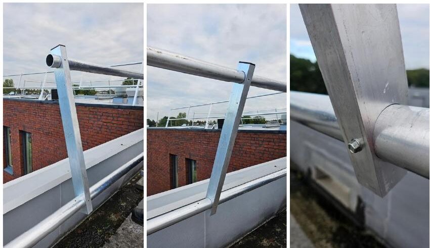
Step 11Mount the intermediate upright in the same way as the normal upright 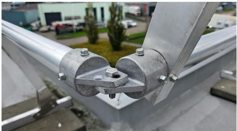
Step 12Use 4 screws and one bolt with nut per corner section. 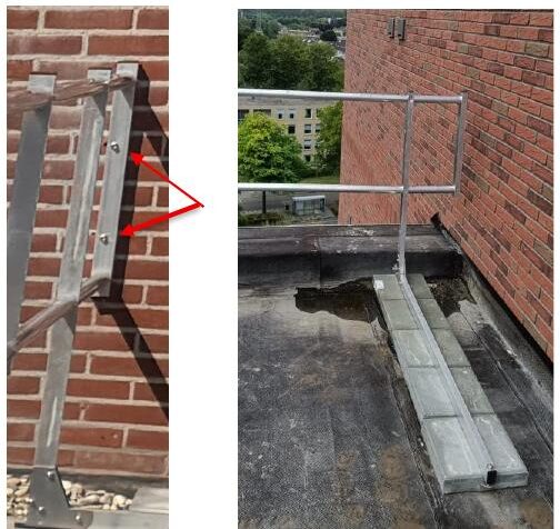
Step 13Wall fixed end section, free standing end section. 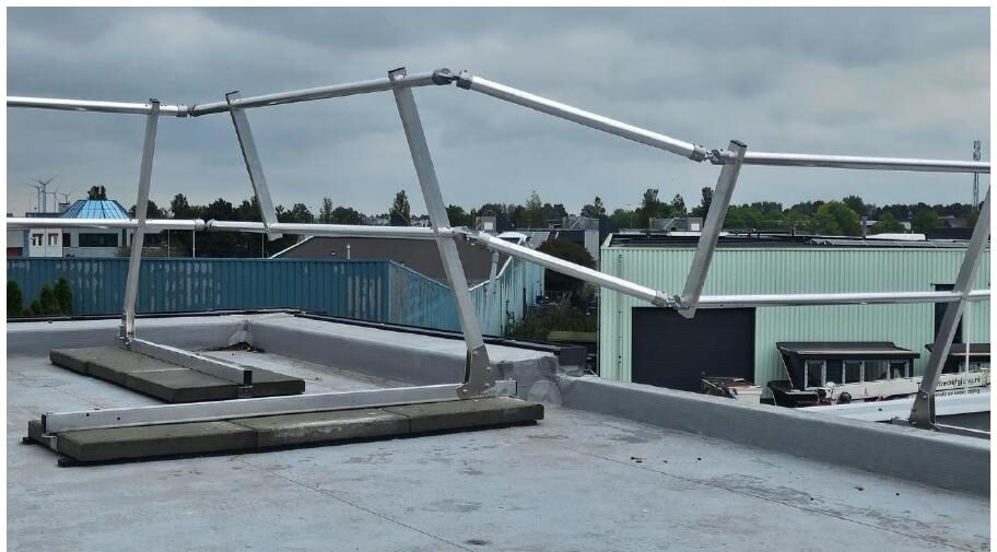
Step 14Finaly double-check and tighten all bolts and connections before completion.


Steps and drawings together: open the installation manual.
intended use and standards
From the certificate page of the same manual, verbatim. The manufacturer declares these only “provided that they are installed and applied in accordance with the manufacturer’s instructions”.
| Intended use | Relevant standard |
|---|---|
| Temporary* edge protection for roofs with a pitch up to 10° | EN 13374:2025 |
| Permanent means of access to machinery | EN-ISO 14122:2016 |
| Permanent** edge protection for roofs with a pitch up to 10° | EN 1990:2025, EN 1991-1-1:2019, EN 1991-1-4:2011 |
* Temporary: exposure period < 6 months, max wind loads up to 600N/m²
** Permanent: design working life of 50 years according to EN 1990:2025
what this page does not tell you
Ballast quantities, wind loads and the imposed-load cases are not in the installation manual and are not guessed at here. They live in the declarations of performance — see the DoP tables and the rest of documents. What the 70° and 90° in step 7 mean is explained in 70° and 90° explained. For anything the documents do not answer, ask us.
Source: Protector Guardrail D228 installation manual, 10-2025 (PDF). Transcribed mechanically at build time; the PDF remains the authoritative document.